Before you start drawing, you should position a distributor and connection unit for these pipes. The architectural basis in DWG format does not have connection information for DDS-CAD pipes, and you will therefore be able to define the pipes more rapidly if you have already got the connection points.
Pipe in pipe manifold is parametric. This means that you can define and edit yourself. In the next example we are going to create a manifold called My own manifold. This has the NRF number 7777777, is 750mm wide, 100mm deep and 350mm high. It is supposed to have 10 tees, and the connection dimension is to be 15 mm.
Find Manifold under Default Tools.
![]()
Default Tools, distributor.
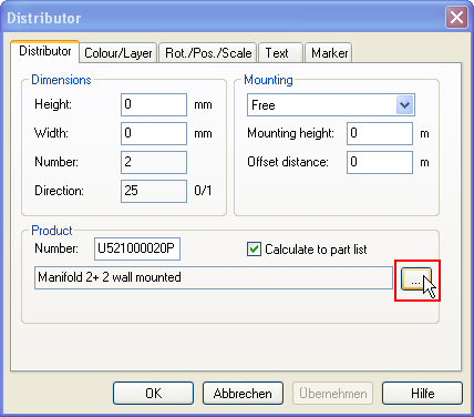
If the product database does not display this directly, get the property box for pipe in pipe manifold, press ... to open the product database.

Properties dialog box for distributor pipe in pipe and under floor heating distributor and connection units.
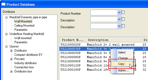
When the product database is displayed, find a distributor near by. Click the right button and select Copy from the pull down menu

Click the right button and copy.

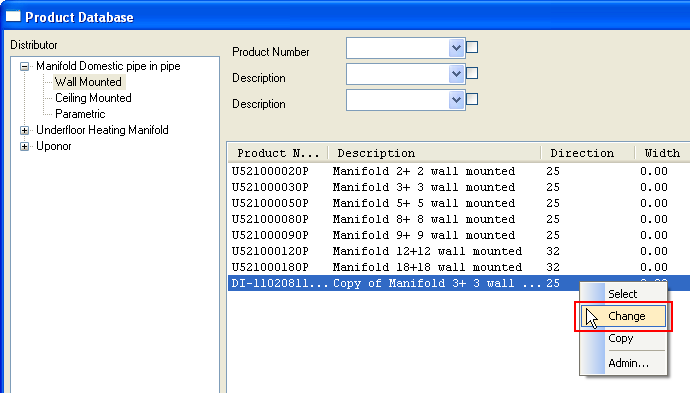
Click the right button on the copied distributor and select Change.
Click the right button and Edit

|
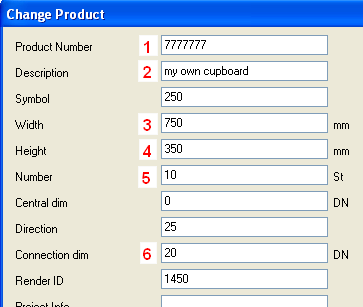
1 – NRF number = 7777777 2 – Description = My own cupboard 3 - Width = 750 mm 4 – Depth = 100 mm 5 – Height = 350 mm 6 – Number of tees = 10 7 – Tee dimension = 15 mm |
Properties for manifold.
The same procedure is used to create individual under floor heating manifold and other distributors.
A separate scheme module is available in DDS-CAD. Here scheme symbols and pipelines can be defined. First, define the storeys with lines, then enter the symbols, and at last the pipeline.

Click to see a video
Principle scheme/system scheme has the same procedure. First, draw lines, and then insert symbols.

Click to see a video
< Previous Section - Next Chapter >